
EDIT: I have devised a new installation method that is many, many times easier, using the current (somewhat flawed) VirtualCables!
1. Installation 2.0
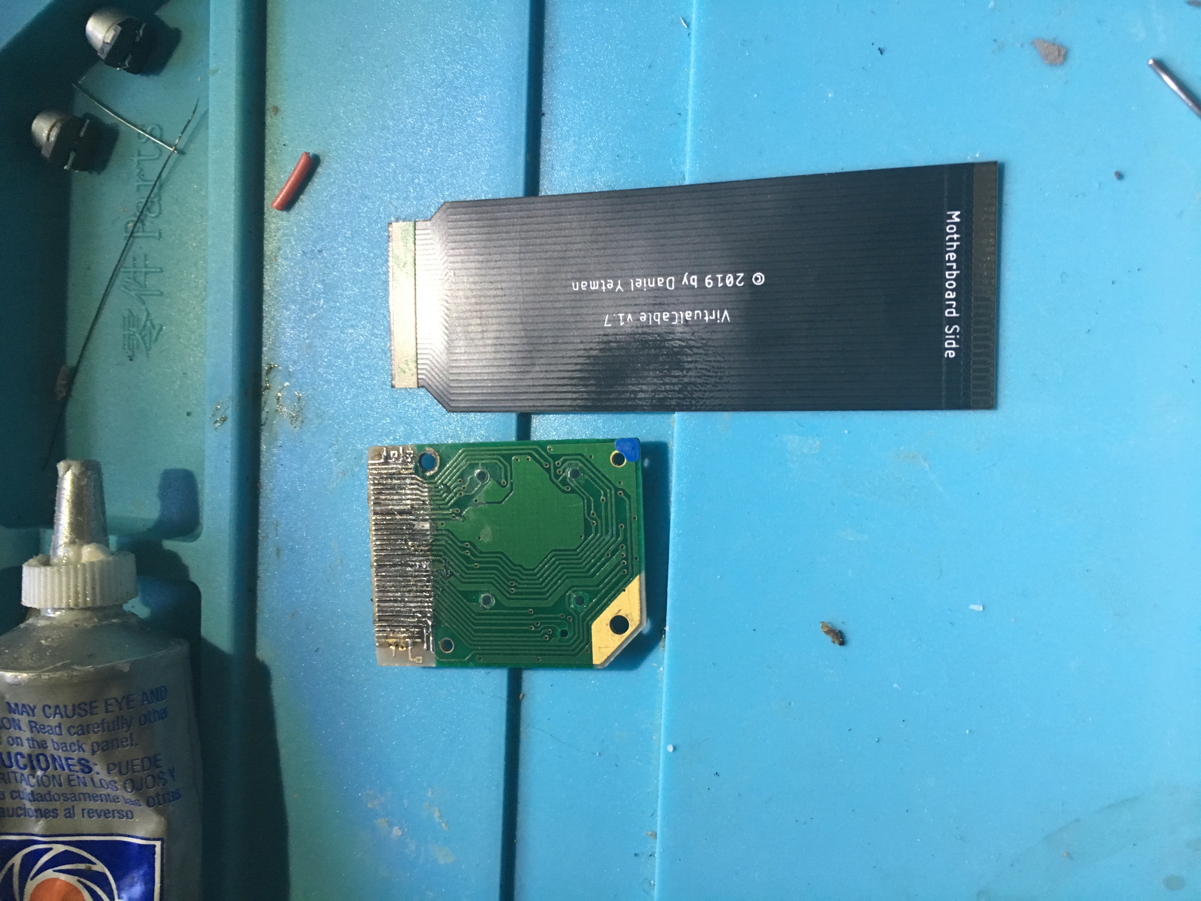
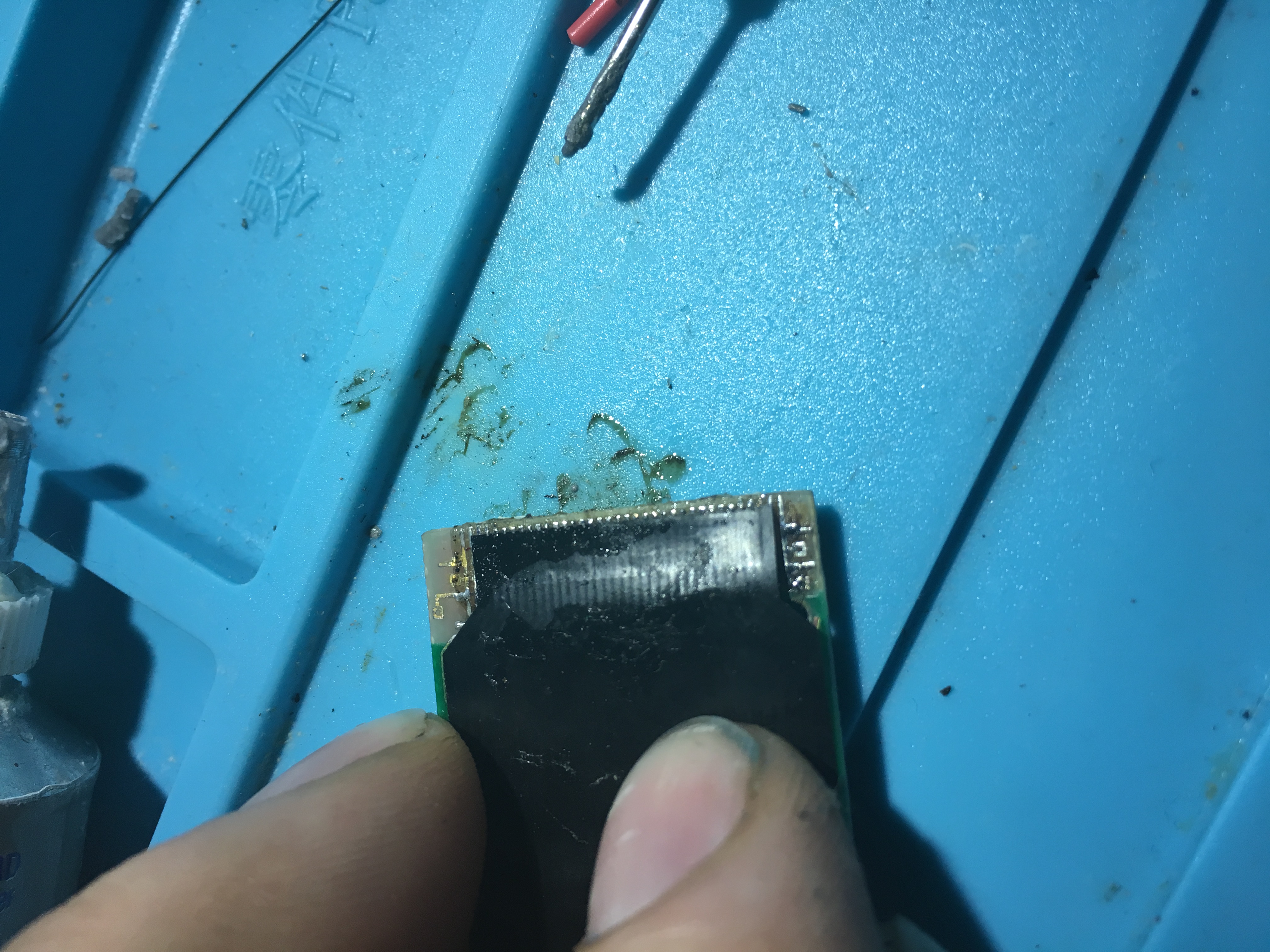
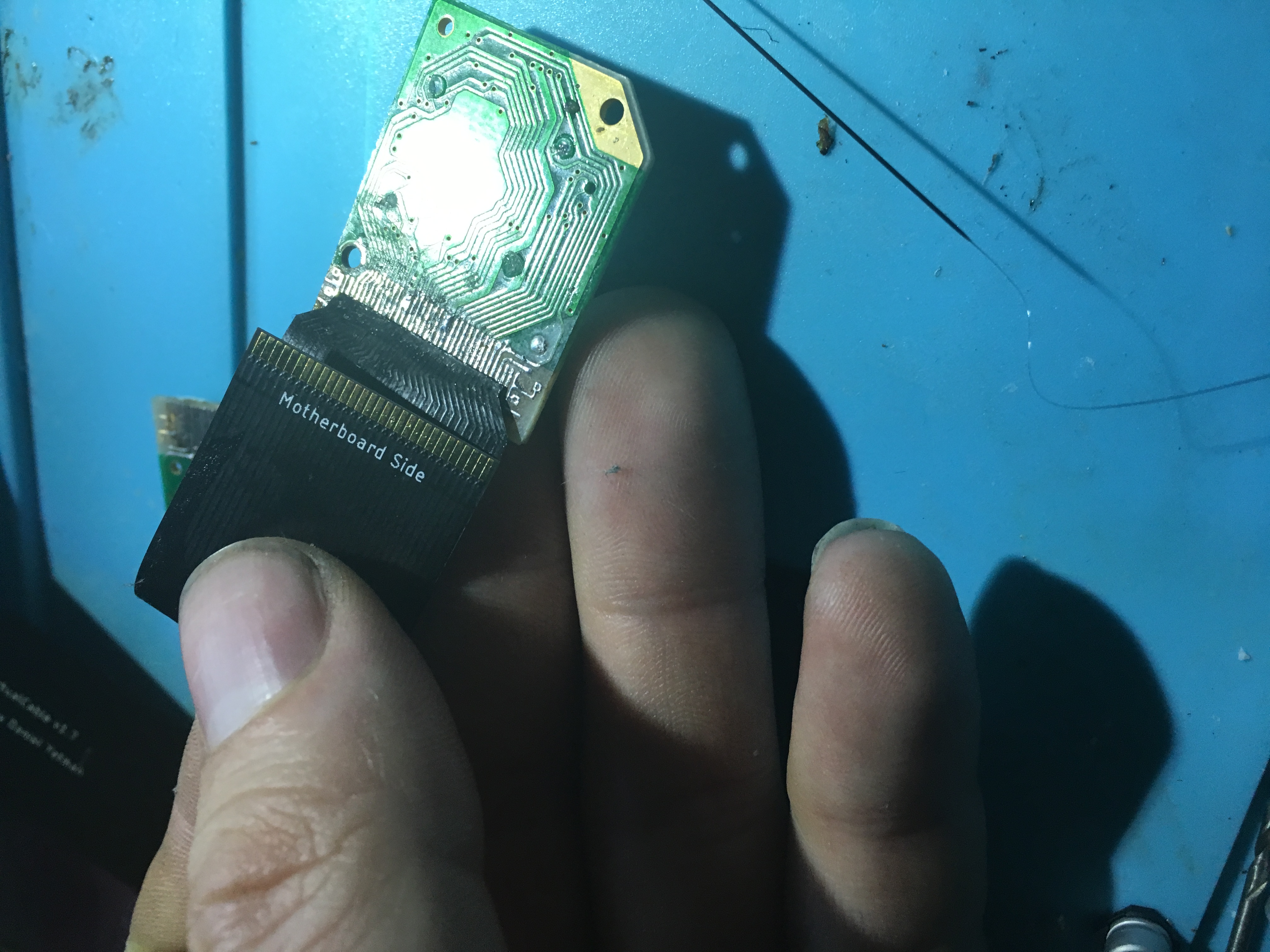
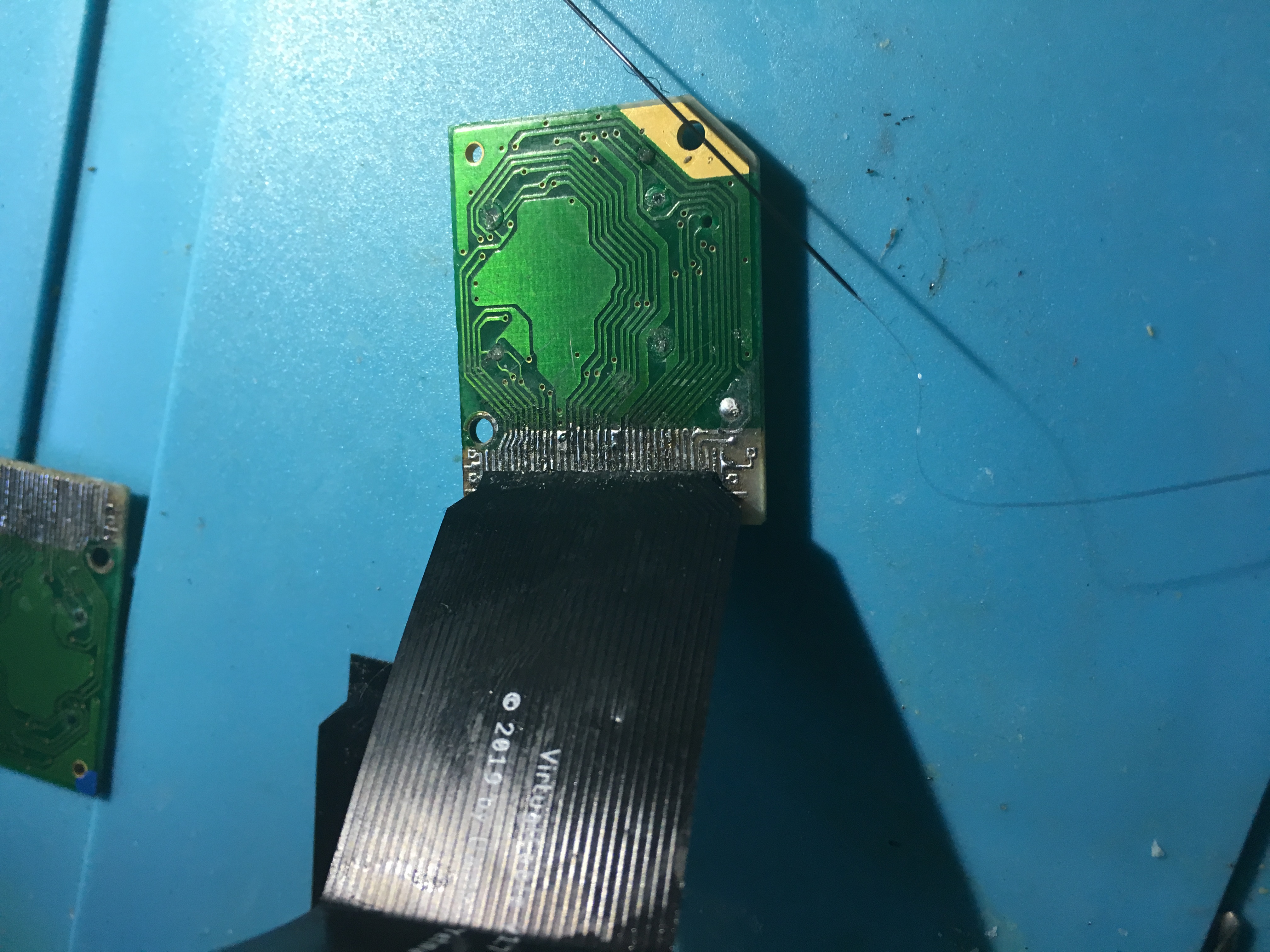
Here we have the LED Board from the Virtual Boy along with my Virtual Cable. You’ll notice that the LED Board is pre-tinned with solder. Don’t forget this step – it’s critical for a good connection!
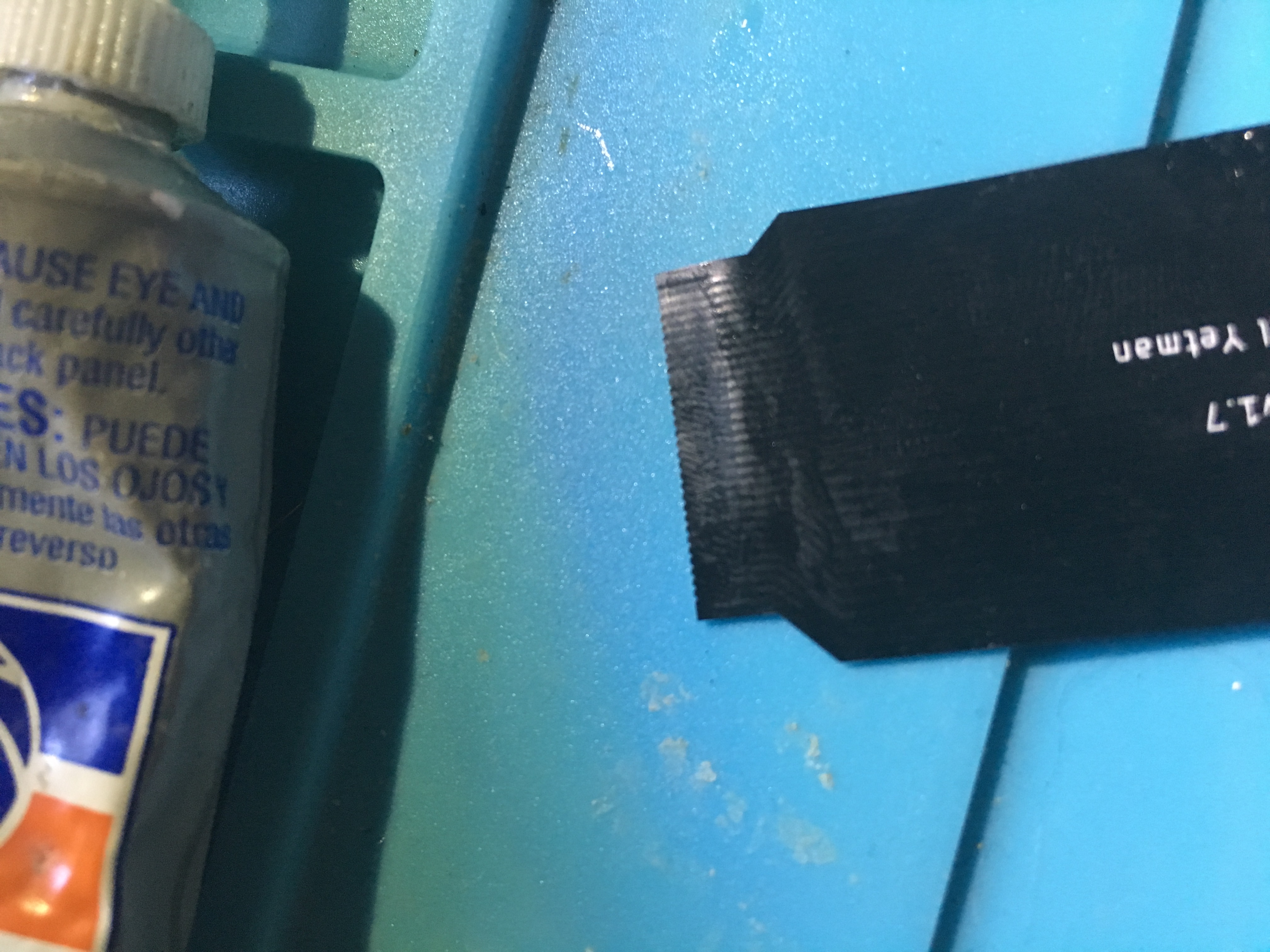
2. Removing the Glue Strip
Unfortunately, the glue strip that I had intended for ease-of-installation turned out to be somewhat less helpful than I’d wished. TIME TO REMOVE IT! Peel the protective film off the VirtualCable, exposing the glue strip.
Douse the area with Isopropyl Alcohol and wait 15-20 seconds. The IPA will dissolve soluble components of the glue, turning it from a sticky strip into a gloppy, barely-adhesive mass.
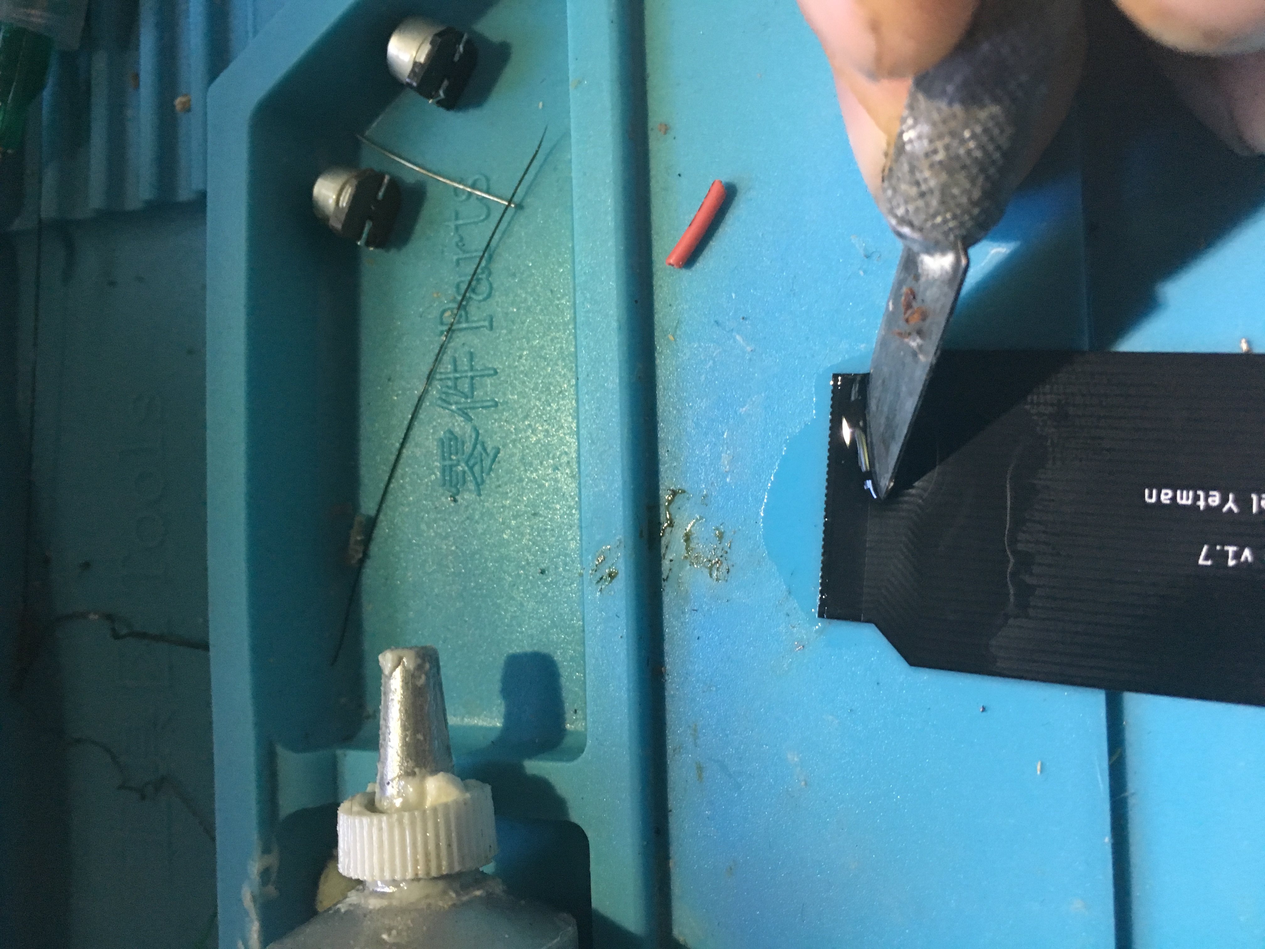
Using a dull craft knife or a hard plastic edge, scrape the dissolved glue gently away.
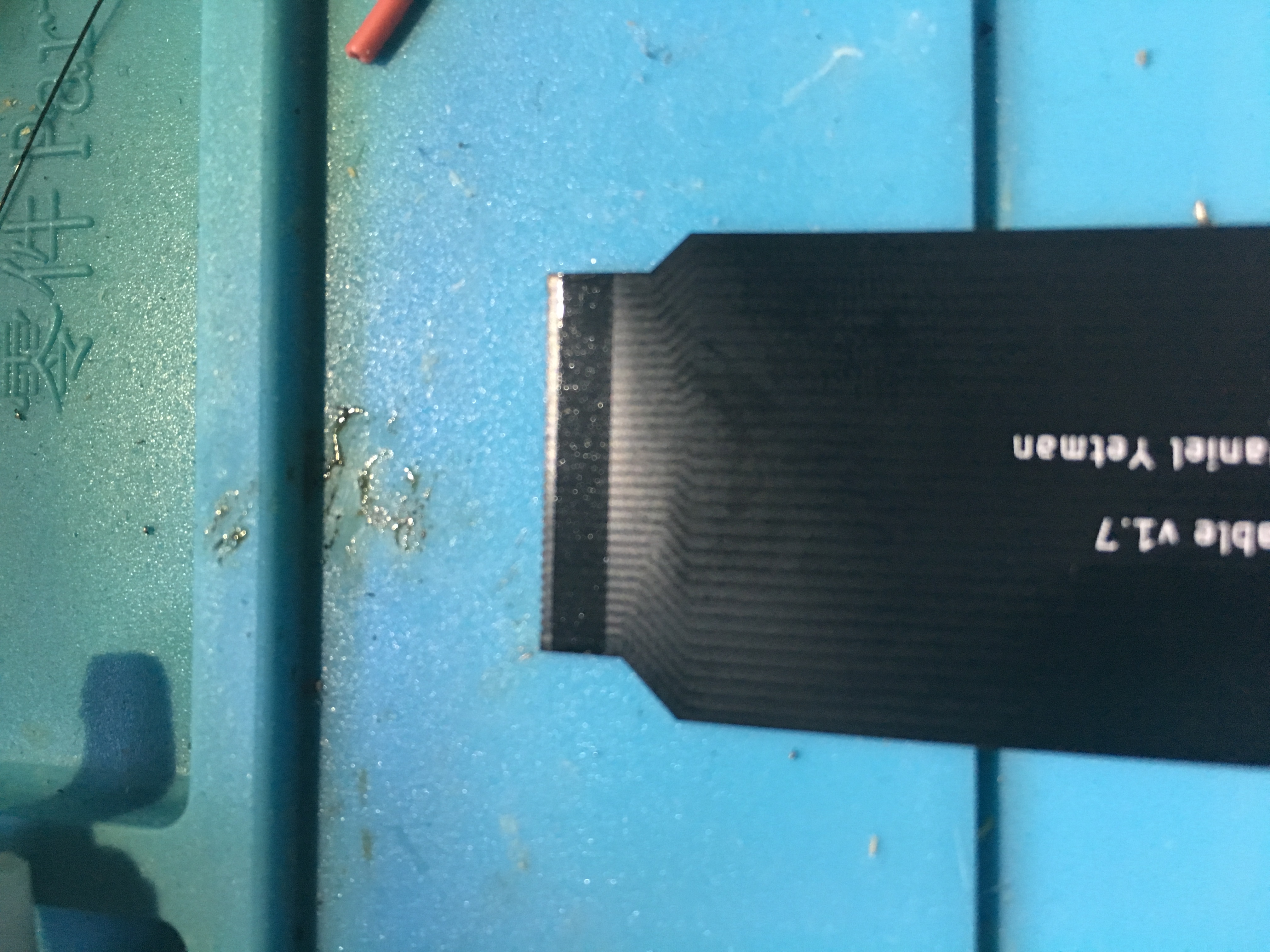
You should now have a perfectly clean and glue-free cable.
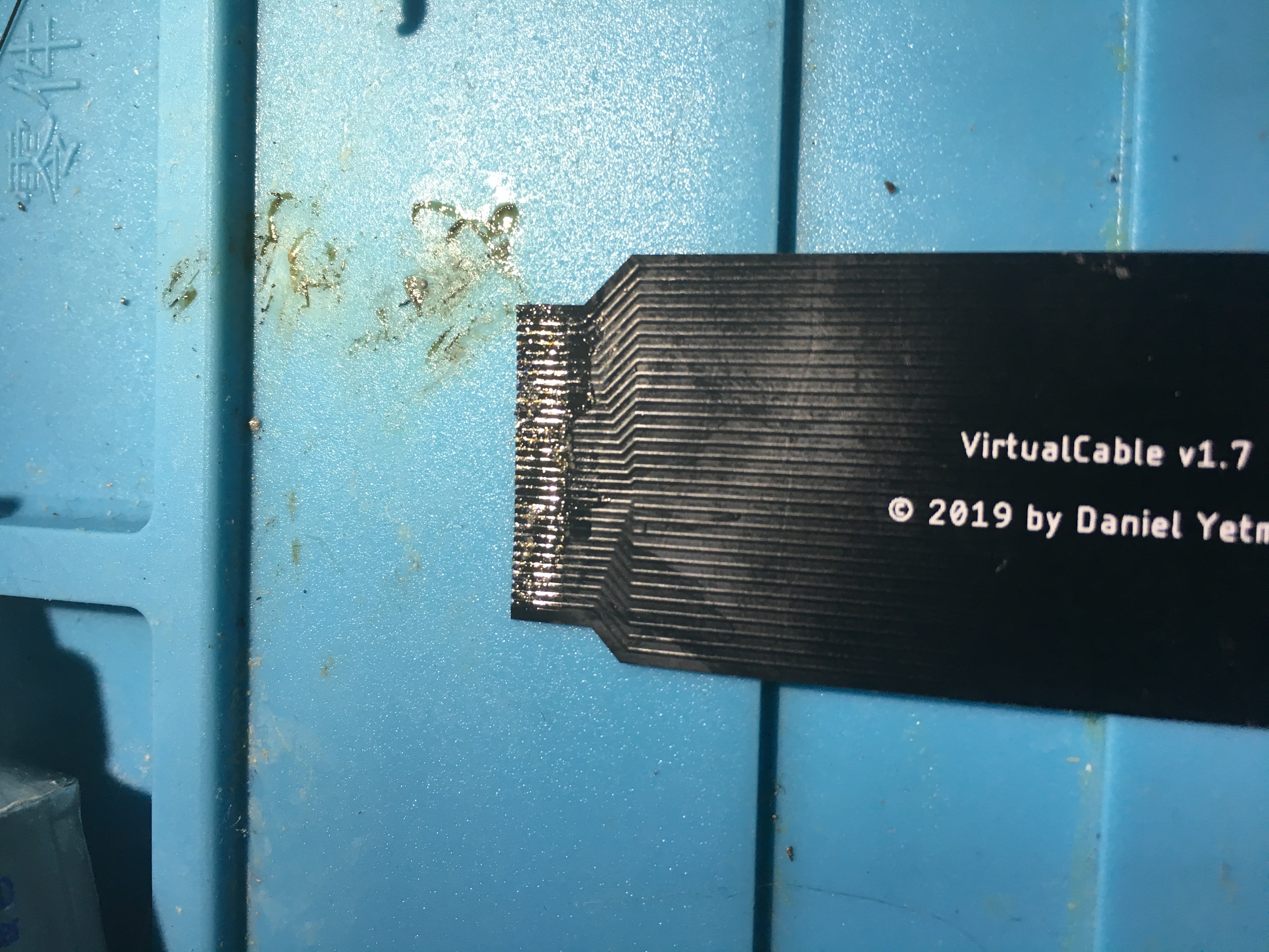
3. Tinning the Cable
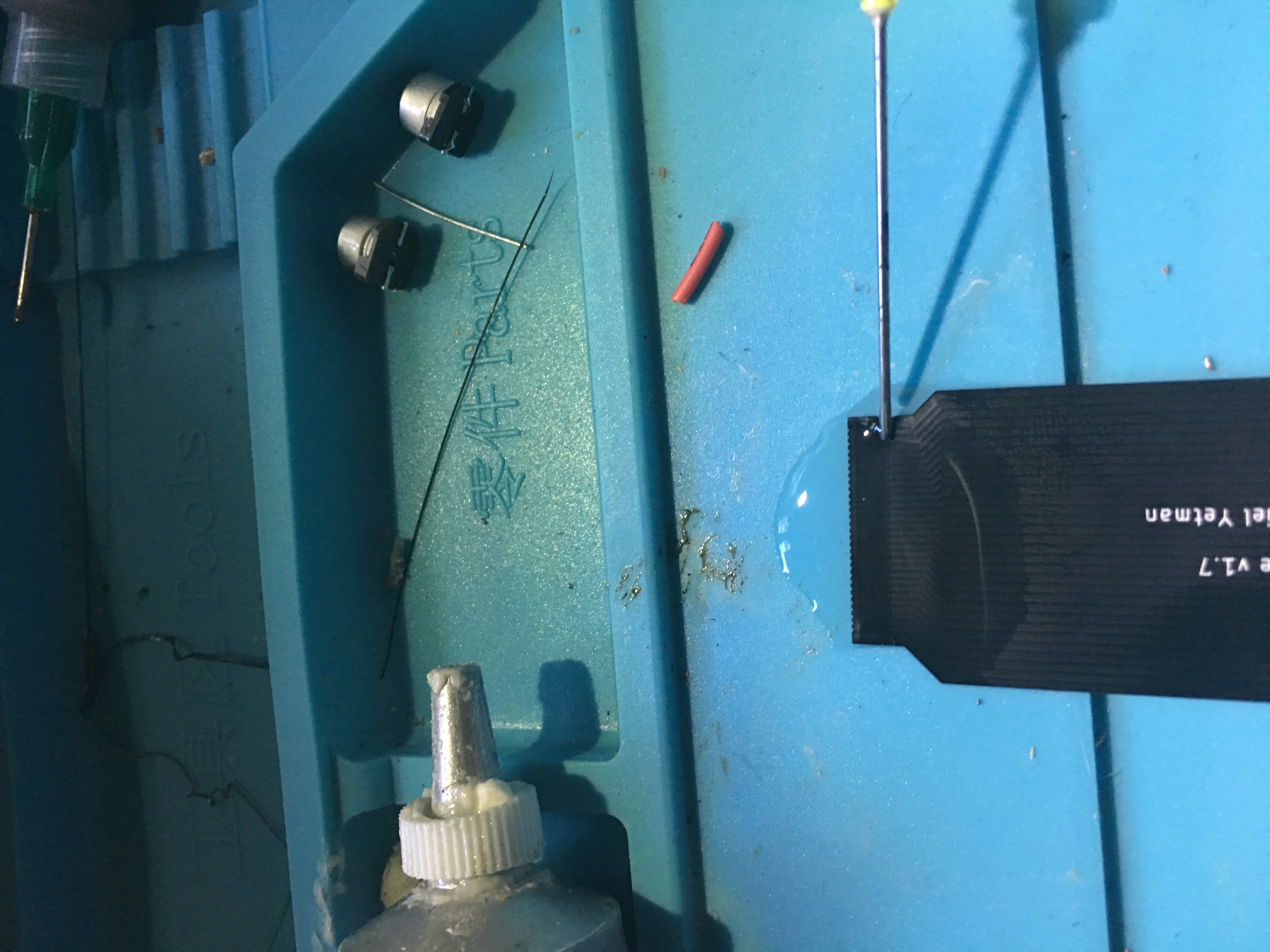
You’ll need to pre-tin the VirtualCable board-side pins. While regular solder and plenty of flux will serve you well, I’ve found that laying a strip of solder paste from a syringe produces superior results. If you choose this method, lay the strip of solder paste across the entire length of the board-side pins, preferably as far back from that end as possible. Then either use a heat gun to melt the solder paste or touch the tip of your soldering iron to the far edge of the pins, which will melt the solder nicely and create a visible mass of solder on the pins.
If you choose to use solder wire for this step, turn your iron down to the lower side of your solder’s melting point – the VirtualCable is very heat-resistant, but high temps can still damage it.
4. Aligning the Cable
Flip the VirtualCable over so that you’re looking at the back. The idea here is that you will be soldering the Cable ‘backwards’ on the LED Board, and then you’ll bend the cable back over itself.
Using the castellated holes as a guide, align the reversed cable’s outermost pin with the fourth LED Board pad from the outside edge. To be very specific, there are three unconnected pads on either edge of the LED Board that we do not want to solder to.
MAKE SURE THAT THE CABLE RUNS PARALLEL TO THE EDGE OF THE BOARD!!! If the cable is not parallel, signals may accidentally connect and short out.
5. Tacking the Cable in Place
Using a broad chisel tip, carefully press down on one edge of the cable above where a solder pad would be. This technique abuses the heat-resistant properties of the cable in order to melt the solder on both pads, joining them together. Depending on the melting temperature of. your solder and the heat of your iron, it may take a few seconds, but DO NOT USE HIGH TEMPERATURES HERE. As previously mentioned, high temps can damage the cable, no matter how heat resistant it may be.
Once one side is tacked into place, do the same to the other edge. With both edges soldered, you can now use the broad chisel tip to do the same thing to the whole width of the VirtualCable, reliably joining all the pads without a tenth the difficulty of the original method.
6. Bend it Like Beckham
Bend the cable over the solder points, and then bend the cable at the midway point BACK again, like so:
You can use a multimeter and the exposed pads to check for continuity to ensure that all connections are solid. If a connection isn’t present, just use your iron on the solder point to re-flow the solder and create a solid connection.
7. Congratulations!
You now have a working VirtualCable with a fraction of the difficulty of the original method!
-
This topic was modified 4 years, 9 months ago by
 RetroDan.
-
This topic was modified 4 years, 9 months ago by RetroDan.
-
This topic was modified 4 years, 9 months ago by RetroDan.
-
This topic was modified 4 years, 9 months ago by RetroDan.
-
This topic was modified 4 years, 9 months ago by RetroDan.
-
This topic was modified 4 years, 9 months ago by RetroDan.
-
This topic was modified 4 years, 9 months ago by RetroDan.
-
This topic was modified 4 years, 9 months ago by RetroDan.
That is cool.
The Tutorial is also very good.
(What is you problem with the 6s? It makes very good pictures for its age. 🙂 )
However, the connections are really small/thin.
The cable itself is a absolute plus but the whole is not for a beginner as @RetroDan already pointed out. If you have never used a soldering iron before, please do not start with this job here. That would be very unwise XD
@RetroDan, for the tutorial it would be good to know what kind or soldering iron you have used and what temperature.
I’ve been contacted by at least one user who has informed me that they had difficulties installing the VirtualCable, in that they could not form a solid solder bridge from board to cable. I wouldn’t give it much credence if it were not someone who is a professional.
That bothers me a little bit. I mean, I had some trouble with it, but I’m by no means an expert. But if an expert has issues, what does that mean to the amateur?
Fortunately, this user relayed to me that they arrived at an unorthodox solution.
By bending the cable pins in half underneath themselves, this user was able to create a solid connection.
I think that, if there is interest in a second run, that I will remove the castellated holes idea and try for a less finicky solution. Turns out 0.6mm pads are a little too small for castellations to be as helpful as I had first imagined.
My apologies, everyone.
I am starting to doubt my abilities here. I have very minimal soldering experience. The only thing I’ve ever soldered was a PlayStation modchip, so how much would it cost to send you my parts to do the mod for me?
RetroDan wrote:
I’ve been contacted by at least one user who has informed me that they had difficulties installing the VirtualCable, in that they could not form a solid solder bridge from board to cable. I wouldn’t give it much credence if it were not someone who is a professional.That bothers me a little bit. I mean, I had some trouble with it, but I’m by no means an expert. But if an expert has issues, what does that mean to the amateur?
Fortunately, this user relayed to me that they arrived at an unorthodox solution.
By bending the cable pins in half underneath themselves, this user was able to create a solid connection.
I think that, if there is interest in a second run, that I will remove the castellated holes idea and try for a less finicky solution. Turns out 0.6mm pads are a little too small for castellations to be as helpful as I had first imagined.
My apologies, everyone.
i just wanted to add. use some tweezers to bend the contacts. it make it easier and and once bent over flatten with a cylinder object like a roll of tape on a hard flat surface. but be careful not to press too hard as you can break the little contact on the ribbon cable. i made that mistake and had to bridge it with a very tiny wire. which is not easy lol. AFTER ALL THAT TAKE SOME KAPTAIn (or scotch) tape and place it over the front and back of the cable to ensure it doesn’t break from moving the ips ajustment over time.
EDIT: I have devised a new installation method that is many, many times easier and 100% reliable, using the current (somewhat flawed) VirtualCables! Please check the first post of this thread.