
Hey all,
As we have the option to use a battery pack, I was thinking about fabricating something that will switch over from an adaptor to batteries as soon as the adapter power goes out without the VB resetting. Does anyone know if that is technically possible and can provide me with the a list of technical hardware required for this? Then I can make up something to apply it on the VB myself and will share that with you all of course!
Since a few months there are Alkaline rechargable batteries available at 1.5v each, so that would work perfectly fine with the VB. I already tested the batteries with my VB and they went on working for over 5 hours! The reason I want to make such a construction is that I have been playing Galactic Pinball to the extreme (as you all probably have noticed lol). This involved leaving the VB powered on a few days as I didn’t have the time to play all day hehe. BUT I always had the fear of a power outage, especially when I got close the the 999,999,999 mark. So when having a battery pack as backup that will switch automatically that would take away that stress 😉
Thanks in advance!
EDIT:
I know it will probably be an ugly piece of equipment, but I just want to make such a thing for when I plan on playing like a madman and set some extreme highscores 😎
Usually this type of circuit is used on clocks, where the real-time-clock chip needs to be powered by a battery if the wall wart fails/power goes out.
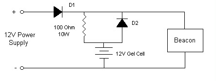
An easy way to do it is by connecting the battery and the adapter in parallel, and protecting the battery with a fast-switching diode, such as a schottky diode. Here is a circuit example to see what I mean:
The voltage output of the adapter should be greater than the voltage of the batteries wired in series. So, if you are wiring 6 AA’s in series you have approx. 1.5*6 = 9V. This means the adapter should output more than 9V for this circuit to work. I haven’t taken a multimeter to my VB adapter so I can’t confirm this. Keep in mind that the voltage a battery puts out decreases over time, so you most likely won’t get 9V (which is good, in this case).
*Note* If you’re using rechargeable batteries, the equivalent voltage of the battery pack will be significantly lower than 9V, probably around 7V. Then you’re fine with the standard 9V output of the adapter, but again, I don’t know what the VB adapter puts out so you’re probably fine either way.
The way it works is when the AC adapter is plugged in, it puts the diode D2 in reverse bias, and the battery is essentially disconnected from the circuit, so the VB is powered through the adapter and D1. Schottky diodes have a low forward voltage drop of around ~.2V, so it will not affect the VB in normal operation. Now, if there is a power failure, D2 will now conduct forward current and D1 will be in reverse bias, so the AC adapter will then be disconnected from the circuit and the VB will be powered from batteries. You need a fast switching diode for this so the VB does not sense a change on the V+ rail and reset the game, which is why you should use a pair of schottkys. Then, if the power were to come back on, the original scenario would be true again and you would be running on AC power again, with the battery circuit disconnected.
In the case of the example circuit in this post, the “12 volt power supply” would be your VB adapter, the “12v gel cell” is your AA battery pack (wired in series), and “Beacon” is your virtual boy. I have seen examples with and without the resistor, but I would probably leave it out. 10W resistors are gigantic and cumbersome and it was most likely used as a current-limiter for the battery pack, which you would not want for the VB circuit. Sorry I couldn’t find a better example, I just looked it up in google image search and that’s all I could find for now.
-
This reply was modified 14 years, 1 month ago by
 Vaughanabe13.
-
This reply was modified 14 years, 1 month ago by Vaughanabe13.
-
This reply was modified 14 years, 1 month ago by Vaughanabe13.
Man, you just MADE MY DAY, very understandable and doable for me! Thanks a lot! I will go to the local electronics store tomorrow to get some shottkys 😛
Thanks!
I think an internal modification would be cool (and that’s a very good circuit/description by Vaughanabe13) but you could also just go with a commercial UPS unit. Even the smallest one should be able to supply power to a VB for days–maybe even weeks… Just make sure the switch-over is “instantaneous”.
As an addendum to Vaughanabe13’s circuit, adding one or more large value capacitors in parallel with the battery and AC adapter (with a voltage rating of at least double your AC adapter output) would give you a little added insurance during the switch-over. And if you use electrolytics, mind the polarity.
If you make your own power adapter for the controller you could build this circuit into it and then have the battery attached to it. So controller, adapter-plate (with circuit and connector for power supply) and then battery attached on the homemade plate…
RunnerPack wrote:
I think an internal modification would be cool (and that’s a very good circuit/description by Vaughanabe13) but you could also just go with a commercial UPS unit. Even the smallest one should be able to supply power to a VB for days–maybe even weeks… Just make sure the switch-over is “instantaneous”.As an addendum to Vaughanabe13’s circuit, adding one or more large value capacitors in parallel with the battery and AC adapter (with a voltage rating of at least double your AC adapter output) would give you a little added insurance during the switch-over. And if you use electrolytics, mind the polarity.
Yeah, good call about the capacitor. It’s not really necessary, but if you’re paranoid about losing power during a game it would be extra insurance. If you’re using a large capacitor (maybe 20-50 uF rated for 20+ V) it will most likely be polarized, so make sure you connect the negative lead to ground and the positive lead to the V+ rail (after the diodes in the above circuit).
The way it works is the capacitor will get charged to V+ (around 9V) when you turn on the power, and when the power switches between AC and batteries the capacitor will discharge very slightly to maintain the output voltage of 9V while the switch is occuring. This would be a necessity if you were using regular (slow) diodes, but with schottkys it shouldn’t be an issue.
Also, I think a UPS would be pretty overkill (and expensive) for this application. Those are usually used for servers, automated test equipment, and PC’s that run 24/7.
How about something much simpler… like: http://www.projectvb.com/rechargepack.html . Basically, you just have the battery pack constantly charging, and if AC fails, the battery takes over.
DogP
That’s a pretty sweet hack, DogP. However, I happen to own a game gear rechargeable pack and it’s really bad. The batteries have been cycled so many times I can only play the GG for about 30 minutes before it dies. So yeah, that’s a great idea as long as the battery back does a decent job powering the VB.
Yeah, I wouldn’t recommend using the GG pack… I’d use some real rechargables, but in that configuration.
DogP
I forgot about your battery pack mod, and that it could be charged while running the VB off of it.
I also had no idea you could just hook up an unregulated DC source with a current-limiting resistor to a bunch of (I’m assuming) NiCd batteries…
There isn’t anything special about the AC adapter included with the GG packs, is there? Wouldn’t it just keep charging them, even if they’re full, and overheat/destroy them?
@Vaughan:
Best Buy has one for < $40, which is pretty reasonable. You could also find a free one on craigslist or something and replace the (likely dead) batteries. As far as overkill, you could also use it for other stuff (WiFi AP, cordless phone, other game systems, etc.) so it wouldn't be a total waste... just not a hack 😉
There’s nothing special about the AC adapter… and it kinda keeps charging them, but just at a trickle once the voltage of the packs rises close to the input voltage.
That circuit is used in all kinds of rechargable stuff… and that’s why they usually say not to leave them plugged in all the time if it won’t be used for long periods of time.
DogP
Thanks for all the info, as I can tell I think the first option seems the most viable. I do not like batteries that are constantly charged, especially the batteries that I use, they have a special charger to prevent them form blowing up LOL. So the diode option seems to be best in my situation, soldering in a capacitor wouldn’t be much of a problem and will secure it even more. Because of that I will solder that one in as well.
Still haven’t thought about how I to make it yet, but have some plans. The biggest issue is to figure out how to have all the connections coming together and to get it all in a package. I might even go the controller adaptor cable way and have the battery pack connected externally.
I have one more question, I have made a red circle in the picture that Vaughanabe13 posted. Isn’t the part in the red circle completely redundant? I would think that applying that part would add up the voltage of the adaptor with the voltage of the battery pack. Or am I completely out of line here 😉 ?
Wouldn’t it be just right as in the second picture?
Attachments:


Yes, in my original post I said you should take out the resistor because it isn’t needed. I don’t know where that design came from so I can’t comment on what the purpose of that resistor was.
The resistor is there because that circuit is also charging the battery, limiting the current of the charging. When using the battery if the power supply fails or is disconnected the current flows mostly through the diode.
If you don’t have a rechargeable battery you should not have the resistor there. If you do have a rechargeable battery you may need to adjust that resistor so you get a proper charging current (on NiCd and NiMH it usually says how much on the battery).
The batteries will stop charging when the voltage level is high enough – usually you need to use a few volts higher voltage than the battery uses to be able to fully charge it. So a 12V source can’t fully charge a 12V battery. There’s a threshold you need to get over…
The first diode prevents any current flowing out of the circuit from the battery (to a not connected powersupply for example) the second diode prevents current from flowing into the battery – when using the powersupply.
That’s how I understand it. 😉
Make sure the diodes can handle the current you need, I’m guessing 1A is enough for a Virtual Boy application but don’t be afraid to use components that can handle more.
One negative thing about just using a fixed resistor and a power source to charge a battery is that the current changes while charging. If you measure and set it to a certain value at start it will slowly fall as the voltages on the charging side and what is being charged gets closer to each other – but it works, rudimentary. Not recommended for lithium-batteries though – it could be an explosive experience – I haven’t been stupid enough to try it myself though.
I found this article about using the I/O protection diodes in a microcontroller for a similar purpose. Not really relevant, I just thought it was kinda cool… 😉
Regarding the variable charging current: a good, current-controlled bench supply would solve that problem. I’ve even heard of (but have never tried; because I don’t have one 😛 ) charging Li-ion cells with such a current-controlled supply. This is usually just to trickle-charge them up to a point where they can be safely charged at normal speed with a dedicated charger.
Yup, not that I have “a good, current-controlled bench supply”, who does? 😉
It’s likely one of those is even better than the standard charger. But nowadays there is usually a microprocessor that checks the voltage regularly and stops the charging when done “delta V” is the new “in-word” for chargers when you read tech magazines.
When I did a job for an electronics company they talked about another company’s UPS (I think it was). They checked the charging of the battery at intervals and recharged the battery by sending a pretty large short voltage pulse that fully recharged the battery – neat method…
I’ve charged a pair of NiMH C-batteries for my bicycle lamp by connecting them directly to a 3V powersupply a couple of times… That seemed to work. 😀
Battery charging is a science of it’s own…
e5frog wrote:
Yup, not that I have “a good, current-controlled bench supply”, who does? 😉It’s likely one of those is even better than the standard charger. But nowadays there is usually a microprocessor that checks the voltage regularly and stops the charging when done “delta V” is the new “in-word” for chargers when you read tech magazines.
When I did a job for an electronics company they talked about another company’s UPS (I think it was). They checked the charging of the battery at intervals and recharged the battery by sending a pretty large short voltage pulse that fully recharged the battery – neat method…
I’ve charged a pair of NiMH C-batteries for my bicycle lamp by connecting them directly to a 3V powersupply a couple of times… That seemed to work. 😀
Battery charging is a science of it’s own…
This is EXACLTY why I won’t try to make a charger off of it as well lol! I will stay with the diode schematic and that is IT!
That way I am sure it will work and I won’t hear an explosion in the middle of the night when leaving my VB on for the highscores hehe.
Yeah, if you’re using recharagble alkalines, I wouldn’t use a charging circuit, but if you use NiMH, or especially NiCd, they can definitely take a little abuse.
If you do Lithium, you definitely need a real charger, though places like Sparkfun have chargers for pretty cheap, and a charger and batteries would easily fit in a VB battery box… and have really good battery life.
DogP