
hello,
I have a virtualboy! and it doesn’t do anything, the only thing I know is that the controler gives the power to the virtual boy. and then the virtual boy does nothing no sound and no screen. I have told this before to Rpack an he said that I had the same problem as here (link: click) but since I am not verry good in english (come frome holland). I don’t understand it good. but to me it seems like I have to replace ”Voltage Regulator Module (U8)” is this true? I am going to order a gamebit so I can open up my VB.
kind regards,
Roelvdm3
Have you tried running it with both batteries and AC/DC-power?
Do you have a regulator to replace it with?
Did you order a long enough gamebit to reach the screws in the deepest holes – otherwise it would probably be quicker to modify a screwdriver than to grind off the hex-shaped area of a too short gamebit…
If you turn it on and make sure you do not have any background noises, do you hear the mirrors do their work? It could be just that your screens died and if you didn’t put in the game really tight, it could be that it does not load the game like it should, thus no sound!
BTW, I am Dutch and could be of help if you live near Alkmaar. PM me if you are interested in some Dutch help!
Yes, you should be able to hear a hum from the oscillating mirrors if you have power in the VB.
hi,
I hear nothing, not even the mirors. I have treid both ways, a (homemade) ac adaptor and the batterypack. I have checked the power suply cabel with a multimeter and the controller outputs power. so that makes me think it’s something inside the VB it self. My plan is as followed I open up the VB, solder out the regulator, drive to the neerest electronic store, and buy a new regulator.
Kind regards,
Roelvdm3
Edit:
I am plannig to buy this gamebit.
-
This reply was modified 16 years, 5 months ago by
roelvdm3.
FYI, the regulator isn’t a standard part… it’s a custom switching regulator board that Nintendo made. If you’re good with electronics, you should be able to replace it with a standard 5V regulator, like a 7805, though I’d recommend using a 9V AC adapter with that kind of regulator, because it brings the voltage down to 5V by wasting the extra power as heat.
This will kill batteries faster, and a 7805 will typically stop regulating at ~7V, so it won’t be able to suck the last of the batteries dry. Also, it’ll get really hot if you use too high voltage of an AC adapter (like 12V or more).
If you have a good electronics store, you could pick up a LDO regulator, like the LM1086, which would regulate with a lower input voltage (probably down below 6V), so you could use a 6V adapter, which would reduce the amount of heat.
I don’t know if the original caps on the motherboard are sufficient/compatible for linear regulators, so you may need to install two caps with the regulator (look at the datasheet).
Anyway, the pinout of the Nintendo regulator is:
1-Vin
2-GND
3-PowerGood
4-missing
5-Vout
6-GND
You may be able to tie PowerGood to 5V (Vout), though it may need a delay, since the purpose of it is to hold the system in reset until the power is stable.
You should also verify that the regulator is actually bad… measure the voltage at Vin with the controller on… it should be the same voltage as coming out of the controller. Then measure the voltage of Vout… it should be 5V, if it’s not, your regulator is probably bad, or something is shorted on the board and overloading the regulator. There should also be a small red LED lit on the regulator when it’s on.
DogP
I think that one only has about 20mm of the thin area and full length is about 50mm – the thick area won’t fit in the hole which is about 48mm deep.
Here’s a longer version:
http://www.classicgamesource.com/proddetail.php?prod=309589004&cat=100&PHPSESSID=45548ee98830ed1d9a399934398dc4c4
I’m not sure it fits without modification either though.
If you grind the edges off and make a trace on the top of the gamebit you can use a plain screwdriver to twist the bit.
You could perhaps use a regulated 5V source and connect it to the 5V and GND of the controller connector or inside the controller, there’s a schematic here:
http://www.goliathindustries.com/vb/VBDiagrams.html
And see if you get any life out of it before you strip the whole thing down.
DogP has a guide here were a bit is adapted:
http://www.projectvb.com/tech/securitybit.html
And disassembly instructions:
http://www.projectvb.com/dissect.html
I’d go for the modified screwdriver rather than spending $10 on something that needs a whole lot more modification.
There are of course fixed screwdrivers with that kind of gamebit head, but I haven’t seen any lately.
Here’s one that advertises that it’s supposed to fit Virtual Boy:
http://cgi.ebay.com/ws/eBayISAPI.dll?ViewItem&item=160405602540
It looks the same as the “longer version” I linked to above.
I treid putting 4,5 and 6v directly into the virtualboy but didn’t help…
I see (read) that the nintendo regulator has 6 pins I am looking now at a 7805 regulator and it only has 3 pins what will be the wirering then? 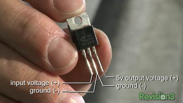
Well… there’s really only 5 pins… pin 4 is missing. But you should connect 7805 input to pin 1, 7805 ground to pin 2 and pin 6, 7805 output to pin 5 and pin 3 (though pin 3 may need a delay, so check this if it doesn’t work).
DogP
hi,
thanks for the fast responses, I read them over and saw you also mentiond LM1086 you sad it would produce less heat. Is the wirering still the same then?

You also mentiond that, I micht had to install 2 caps. what are these? (said I am dutch so I won’t understand everything in english).
Kind regards,
Roelvdm3

The pinout of the LM1086 is different, but it would be connected the same way (input to Vin, ground to ground, output to Vout and PowerGood).
But both regulators are linear regulators, so the LM1086 would only make less heat if you use a lower input voltage. And yes, you may need a capacitor on both the input and output.
DogP
hi,
(We’re almost there) what kind a capacitor do I need (a modelnumber?)
-
This reply was modified 16 years, 5 months ago by
roelvdm3.
7805 datasheet: http://www.national.com/mpf/LM/LM78M05.html#Overview
LM1086 datasheet: http://www.national.com/mpf/LM/LM1086.html#Overview .
From reading those, it looks like you’d be fine with no capacitor on the 7805, and probably just one 10uF tantalum capacitor on the output of the LM1086. Like I said though, no capacitors may be necessary, since there’s other capacitors on the motherboard for this purpose already.
DogP
Hello! I’m part of the Makers Local 256 hackerspace and have access to an electronics lab and a ton of people with EE degrees and lots of experience with soldering. So my original Virtual Boy that I bought on clearance at Walmart when I was a kid back when they first stopped making them finally quit working for me. It has the same “does nothing” when you turn it on problem. I bought some screwdrivers on Amazon to open it (they worked PERFECTLY):
Then I turned on the power from batteries in the remote and saw the little red LED light up on the corner of the U8 DC to DC converter module just like discussed here. I then took a meter and measured (careful to pick the right pins and not short out the whole thing) ground to Vgood and ground to Vout. It turns out that both Vgood and Vout are both producing the ~8V that come in through Vin. So it looks like this module isn’t doing the ~8V to 5V step down that it was built to do.
I went on eBay and bought two more base units for around $30 for one of them and $80 for another with three games. They both work perfectly! I’ll use the meter to see if the Vgood has any sort of delay when it turns on and report that back here.
So now today I get an email from element14 and see that they have tiny voltage regulators. After reading the datasheet it looks like I can just replace the U8 module completely with one of these and it should be good to go! I’ll give it a shot this weekend and let you know how it goes!
http://www.newark.com/nxp/nx1117c50z-115/ldo-fixed-5v-1a-sot-223-4/dp/66W5705
If you replace the switching DC-DC regulator with a linear regulator, be sure you heatsink it well (especially that small of a package), because it will be making a decent amount of heat. I’d guess typically around 1 – 1.5 Watts of heat. Also, if you run on batteries, your battery life will suffer.
Since that regulator is an LDO, it’d probably make sense to lower your input voltage, so it generates less heat (either replace one battery with a dummy, or use a lower voltage wall wart). If you use the standard power supply/batteries, you might as well just use a 7805.
Though if you’ve been getting 8V on the 5V rail, your electronics may be toast anyway. :/
DogP