
Also, I can’t really tell the difference between the screens, DogP. I guess I don’t really know what an autorouter looks like since I have usually done stuff by hand. When you have boards that dense, you’re going to have a lot of random vias and strange looking traces no matter what you do.
Vaughanabe13 wrote:
Also, I can’t really tell the difference between the screens, DogP. I guess I don’t really know what an autorouter looks like since I have usually done stuff by hand. When you have boards that dense, you’re going to have a lot of random vias and strange looking traces no matter what you do.
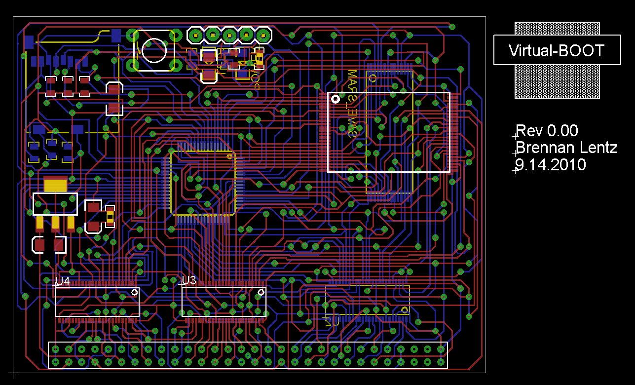
Yeah, your PCB is definitely very dense, and I’d expect some randomness, but typically humans route traces in meaningful paths, while an autorouter picks short, direct, odd shaped paths… and things like a bus going from one chip to another many times won’t even run parallel to each other, even though they’re consecutive on both chips.
The original Flashboy isn’t THAT dense… look at all the extra unused space (especially on the final: http://www.planetvb.com/content/hardware/flash_carts/flashboy/images/fb_final_2.JPG ), but in the first one I linked to, there’s random traces and vias all over the place. The second one I linked to actually has tighter routed traces without using vias every 1mm 😉 .
So anyway… does it actually look routable on two layers? I don’t like 4 and 6 layer boards, but that’s always an option. Another option would be jumper wires for things like Vcc and GND, just to remove the need for those to snake across the board. Also, have you considered using a CPLD as a crossbar? The extra space taken up by the chip would probably more than make up the amount saved from routing.
DogP
All revisions prior to the final version where done with the Eagle router. I decided to buy Electra when Eagle was failing / taking forever.
It’s also cheaper to manufacture if there’s less vias.
using the auto-router… all the ones that I’ve used have sucked, and even if they do route, they look like crap 😉
Doesn’t really matter what it looks like as long as it’s all connected up.
If you spend some time tweaking the settings you can get very close to the look of a hand routed board. Electra can be made do some really neat bus routing.
Vaughanabe13 wrote:
I think the routing is almost done.
Very cool… that’s looking nice! BTW, what’s with the edge connector? How do you plan on doing through hole? A standard VB connector has SMT pads, and it straddles the PCB. Even if not using the original connector, I’d think you’d want to do it that way as well, since a right angle connector probably wouldn’t fit (the board would be too low and hit the case).
DogP
Yeah, I’m already aware of the edge connector problem. I’m currently looking for a replacement part, either through hole or smd, and right now i have some more connectors I need to test. Yes I know the VB connector is straddle mount but there are no replacement straddle mount connectors in existence that will work. I am prepared to switch the connector footprint to smt if I need to, but first I need to figure out a solution to the connector problem. Hopefully my next parts order will shed some light on that.
To add to that, I understand that using a through-hole or SMD connector like that would make it so the PCB wouldn’t fit in a regular VB cartridge case. I ordered a connector that I’m *hoping* will work as a saddle-mount connector, because it’s a straight-lead through-hole connector and I’m planning on bending the leads and mounting it saddle-style instead of through-hole. If I can make that work it might be the best solution for not having to use an original VB connector. And, if someone wanted to use an original VB connector that would also work because the SMT footprint would be the same either way. That would be the ideal situation for me but again, these are just theories floating in my head and I won’t be able to test them until my order gets here.
The worst-case scenario here would be that I stick to the current through-hole footprint and use a board-mounted through-hole connector. I would be able to fit the board in the VB, so functionally it would still work, but it wouldn’t fit in a standard VB case so I would either need to come up with some kind of custom mold (very doubtful) or it would just not have a case. I understand a lot of you would like it to have a case so that’s why I say it’s the worst-case scenario. I’m planning on releasing everything at the end so maybe I’ll just make two versions of the PCB and let you guys choose what kind of connector/case combination you want to use.
As far as profit and release goes, I guess what I could do is:
1) Release my firmware hex files, PCB gerber files, bill of materials, etc. So those of you like DogP that are DIY people can actually make the cart yourselves.
2) Alternatively, I could build up cartridges for people and charge maybe $10 more for the labor.
3) Add a link to my Paypal account so people could donate a couple bucks only if they want to.
I fully support all of those options, (they’re not really mutually exclusive) plus I recommend a fourth:
Sell a board and a set of parts as a kit so that the “not quite DogP level” DIY’ers 😉 can assemble their own without having to source the parts and etch/order a PCB.
Also, that board is a work of art! Brilliant job (once you get the connector part squared away, that is ;-))
RunnerPack wrote:
I fully support all of those options, (they’re not really mutually exclusive) plus I recommend a fourth:Sell a board and a set of parts as a kit so that the “not quite DogP level” DIY’ers 😉 can assemble their own without having to source the parts and etch/order a PCB.
Also, that board is a work of art! Brilliant job (once you get the connector part squared away, that is ;-))
Thanks! Dense PCBs are like eye-candy to me so I totally know what you’re talking about. Working on it is so fun it’s actually hard to work on other stuff right now, haha.
As far as the PCB ordering goes, I have a meet-you-in-the-middle solution for that. Instead of letting you guys do all the PCB ordering yourselves, I would just put it up for sale through a third-party site like BatchPCB. Those guys let you submit a design and then let other people buy your board directly from them. So all you would have to do as a customer is just place an order for one of my boards and they’ll send it to you. That’s much easier than having to take the source files and send them to a fab house.
Also, this board is nearly ALL surface mount parts (with a few exceptions), so those of you who don’t have access to good soldering stations or know how to solder surface mount parts successfully might have trouble. TSOP48 and TQFP64 aren’t the hardest packages to solder ever, but they definitely require a lot more effort than through-hole, and the cost of the parts is quite a lot, so mistakes are costly. Also, if I sell a kit version I would need to at least put a few parts on the board first, including the microprocessor, and a couple other components related to the micro. This is because not everyone will have access to a programmer or know how to use one, so I will need to program the micros in-circuit before sending them out. But then if I already assembled the micro circuit, it wouldn’t take too long just to solder the rest of the parts anyway, so I’m not sure the kit idea is best. If I didn’t assemble the micro circuit and program it, the kit idea is almost just as DIY as the non-kit idea, because you would have to be able to program the microcontroller yourself. I don’t have an industrial programmer I can use to program TQFP micros so I can’t sell pre-programmed micros.
Vaughanabe13 wrote:
As far as the PCB ordering goes, I have a meet-you-in-the-middle solution for that. Instead of letting you guys do all the PCB ordering yourselves, I would just put it up for sale through a third-party site like BatchPCB. Those guys let you submit a design and then let other people buy your board directly from them. So all you would have to do as a customer is just place an order for one of my boards and they’ll send it to you. That’s much easier than having to take the source files and send them to a fab house.
I forgot about that… that’s a pretty good idea, although, wouldn’t the price-per-board be lower if you just bought a big batch and sold them off piecemeal? I assume you’re going to take pre-orders, so you wouldn’t have a bunch left over…
Also, this board is nearly ALL surface mount parts (with a few exceptions), so those of you who don’t have access to good soldering stations or know how to solder surface mount parts successfully might have trouble. TSOP48 and TQFP64 aren’t the hardest packages to solder ever, but they definitely require a lot more effort than through-hole, and the cost of the parts is quite a lot, so mistakes are costly.
Another good point… I’ve soldered the odd passive (caps, resistors) and a couple of PLCC sockets (poorly :-P). I don’t think I would have any trouble with this, but some might (although why those people would buy the kit, I couldn’t say :-P) Actually, it looks like a fun challenge to solder by hand (or a good reason to finally make a toaster-oven reflow setup 8-))
…I will need to program the micros in-circuit before sending them out. […] I don’t have an industrial programmer I can use to program TQFP micros so I can’t sell pre-programmed micros.
Maybe you could “MacGuyver” up a simple socket using straight-pins and ball-point-pen springs? 😉
If I didn’t assemble the micro circuit and program it, the kit idea is almost just as DIY as the non-kit idea, because you would have to be able to program the microcontroller yourself.
Yes, but my point about not having to find (and have shipped) single/small quantities of (as you’ve admitted) hard-to-find chips is still valid…
I can’t wait to see the parts list. My best guess for the uC is AVR, but there are a lot of other makes it could be.
I’m most interested in the SRAM and level converters, because I’ve had a similar SRAM-based design in my head for years, although mine was/is going to use a standard flash/EPROM/OTP to boot, then use a “Game Genie” type mechanism to swap the SRAMs in after the VB’s running. The programming would be done over the link port or custom hardware in the cart (maybe even Ethernet).
I forgot about that… that’s a pretty good idea, although, wouldn’t the price-per-board be lower if you just bought a big batch and sold them off piecemeal? I assume you’re going to take pre-orders, so you wouldn’t have a bunch left over…
Shoot, yeah, I didn’t think about the bulk discount. You’re right, it would be better just to order a bunch of boards and sell them individually that way. So I could do that and also offer up the PCB design files if people wanted to do whatever with it.
Maybe you could “MacGuyver” up a simple socket using straight-pins and ball-point-pen springs? 😉
It probably wouldn’t be anything reliable. I suppose what I could do is make a quick PCB with a TQFP pad and just physically hold down the chip while I program, but that’s not really easy or very reliable either. A while ago I built a UV-exposure rapid prototyping station that I can use to churn out quick single and two-layer boards, so maybe I’ll do that on a weekend some time.
The best way would be to buy a TQFP socket adapter, but those usually cost >$100. I see one on eBay for 70 right now so I guess that’s doable if I decide to go that route.
Yes, but my point about not having to find (and have shipped) single/small quantities of (as you’ve admitted) hard-to-find chips is still valid…
Yeah, again I forgot about the bulk discount again, good point. Availability shouldn’t be a problem at this point…I have my sources.
I can’t wait to see the parts list. My best guess for the uC is AVR, but there are a lot of other makes it could be.
I personally don’t like Atmel very much. I’m a Microchip guy. 😉 More info on the Micro will come later, but I still have stuff to test before I know for sure what I’ll be using. I will say that it’s a TQFP-64 package and I’m using EVERY single pin. On the one hand I don’t like that there are no free pins, but on the other hand it minimizes the space needed on the board.
I’m most interested in the SRAM and level converters, because I’ve had a similar SRAM-based design in my head for years, although mine was/is going to use a standard flash/EPROM/OTP to boot, then use a “Game Genie” type mechanism to swap the SRAMs in after the VB’s running. The programming would be done over the link port or custom hardware in the cart (maybe even Ethernet).
The level conversion is another thing I’m still working out. I have it all planned in my head so right now I’m building up a circuit to test it. The problem is I don’t really have any TSOP and TSSOP breakout boards, so by the time I order all of those I might as well just order a prototype PCB and test right on the PCB.
Great news! What’s the connector part #? Is it widely available at a reasonable price?
Now we only need to find a way to custom make cart shells. 🙂
Off the shelf connectors, top work finding those, if i can get hold of a CAD model or dimensions i could alter the cart shells to hold this connector in place and totally eliminate donor cart requirements. Well thats the theory.
I think a re-model of the carts is needed before anything gets made, the design can be simplified to take out a lot of details and just custom them to hold this connector and a pcb.
I think having batches of the shells CNC machined would be cheaper than a mold, especially if the shell is simplified. Time is not my friend at the mo but if i get a chance to suss out the connector fitting in a shell I’ll give it a go at modeling them up so quotes can be accurate.
I’ll get you guys the part numbers later today. I wouldn’t say it’s cheap, it’s like $8-9 per connector, but that gets cheaper in bulk. It’s a very simple connector compared to the VB carts so I imagine it would be much easier to make a custom plastic case. I measured the dimensions of my pcb and the width is a little bit smaller than a vb cart case. The length is a bit longer, even after adjusting for the short connector. So that will have to be taken into account.
Honestly I don’t know much at all about designing cases so I would probably leave that up to the vb community.
Vaughanabe13 wrote:
Honestly I don’t know much at all about designing cases so I would probably leave that up to the vb community.
I’m up for doing the design changes etc to get this connector to fit & mount a pcb, might take some time (only cos i got stack of work on) but it’ll benefit us all if we can get completely fresh made cart cases & connectors.
I so want to get Bound High on a dedicated cart, maybe even a clear cart case, just to be a bit flash.
Yeah, a Bound High cart would be cool! I was thinking about making a run of carts with boxes and manuals, but it would not be possible without completely custom parts. Now it seems in reach! 🙂 Maybe I’ll finally get around to releasing BLOX 2 on cartridge?
BTW, how about making dust caps for that connector?
Hedgetrimmer wrote:
Vaughanabe13 wrote:
Honestly I don’t know much at all about designing cases so I would probably leave that up to the vb community.I’m up for doing the design changes etc to get this connector to fit & mount a pcb, might take some time (only cos i got stack of work on) but it’ll benefit us all if we can get completely fresh made cart cases & connectors.
I so want to get Bound High on a dedicated cart, maybe even a clear cart case, just to be a bit flash.
Cool, that would be awesome! Yeah, I have two LEDs on my board right now, one for power indication and one for status indication. I’m using the status LED for debugging but it would be cool to have it flash inside the case while the cart is loading data or something. I think the coolest kind of case would be transparent red with red LED’s. 😀
KR155E wrote:
Yeah, a Bound High cart would be cool! I was thinking about making a run of carts with boxes and manuals, but it would not be possible without completely custom parts. Now it seems in reach! 🙂 Maybe I’ll finally get around to releasing BLOX 2 on cartridge?BTW, how about making dust caps for that connector?
Why would Bound High carts need custom parts?
DogP
Newest update on the PCB is up on my blog. Also, I wrote down all of the information for the VB replacement connector and where you can buy it.
Check it out: Update