

Try carefully inserting and removing the game a few times in a row (straight in and out; no pulling down). It sounds like the problem might be slightly oxidized pins on the cart, the system, or both. If so, this should scrape enough off for it to make better contact. You might have to repeat with your other games. Let us know how it goes.
e5frog is right; the one on the wiki is a confirmed, working pinout. IIRC it matches the one, official cable known to exist.
The sync line does indeed only go from one VB to the other. This is so the mirrors in the two VBs are synchronized, which helps keep the two VBs’ programs in sync (if they’re written correctly; much of the existing homebrew doesn’t use this feature). It’s technically not needed for simple data transfer, but it’s probably a good idea to leave it in.
I agree with HorvatM; without knowing how the firmware in the Retrode decides how big a file should be, any answer given would be pure speculation. It might have a database of sizes which contains an incorrect entry for RA, or it might be using some kind of heuristic which fails with RA for some reason. Is the source-code of the firmware available?
The only foolproof method would be to simply look for repetition in the entire ROM address space (on power-of-two boundaries) and take the repeated block as your ROM. You might also use the data from the header to construct your filename (although I can see how just calling everything “cart.bin” or whatever would make it easier to use with emulators).
litephiter wrote:
I probably could estimate the size of the medallion, but I’m not sure it would be worth the price. To me, it’s pretty amazing that this thing is as complete as it already is.
You’re probably right. However, if you have access to a regular 3D printer, you could print two halves of a hollow one in plastic, then stick a lead or steel weight inside to make it heavy enough. It might be small enough I could print it on my printer (no heated bed (yet) so larger items warp pretty badly).
Or, you could make a silicone mold from a printed part, then cast it directly in lead (and paint it) or lead-free pewter. Still more than you probably want to spend, though.
Nice new profile pic, by the way!
Thanks! I couldn’t have done it without your (nice, in-focus) photo. It’s more impressive at full resolution (I’m lookin’ at you, KR155E ;-))
-
This reply was modified 8 years, 1 month ago by
 RunnerPack.
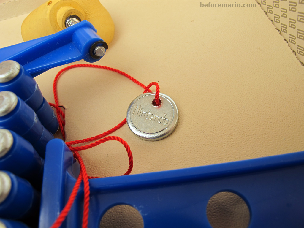
Nice find! I found a picture of the actual medallion:
It would probably be kinda pricey, but you could get it 3D-printed (in metal!) from a place like Shapeways (assuming you had a 3D model of it).
Can you estimate its diameter and thickness from the photo and your actual unit?
Welcome to the site!
Actually, the VB’s native framerate is 50 Hz. It can’t be changed because that’s the fundamental frequency of the vibrating mirrors (they act like pendula). I’ve actually confirmed this by wiring one of the galvos up to a headphone plug and using my soundcard to drive it. It works great at 50 Hz, with a nice loud hum and wide deflection. Even a few Hz off and it barely moves.
Besides, if it’s running fast, it’s because the emulator is using your display’s 60 Hz timing, when it should be 50 Hz (not the other way around, which would make it slow).
Further evidence: when displaying the VB on larger displays at conventions, they used PAL video, because it is also 50 Hz, instead of (59.94 Hz) NTSC (which was the standard in Japan).
Even when I first played WL on hardware, I noticed that the timer seemed to be running a bit fast. I don’t think it’s actually meant to display minutes/seconds (or maybe they just gave up trying to get it to do that).
Thanks again, HorvatM. I haven’t had the time to reply to this thread for a number of reasons, but I am still following it, and I do plan on getting this thing fully set up and usable (including some kind of tracked wand controllers; I’m looking at a single- or dual-camera PS Move setup, at least for the short term).
I bought a new (bare-bones) PC to run VR games on, but I’m having trouble setting it up (two different SSDs I’ve tried are completely undetected by the BIOS). I’m going to go ahead with a mechanical drive for now and just live with the loading times.
HorvatM wrote:
Shouldn’t the SDK be enough for straight C++ development?
As near as I can tell, the current SDK doesn’t support the DK1. I’ve been trying to find a copy of the latest SDK that does support it, but so far it’s eluding me…
Maybe the example code from that book will help, but it’ll probably just rely on me having the SDK files to link against.
Sorry I don’t have time to reply to everyone individually, but I do appreciate the links and info, so please keep them coming!
Another good one is Musagi by DrPetter of “SFXr” and “Sculptris” fame.
Good job on the song, Guy! Do you plan to recreate it for the VSU, at some point?
I’ve never been a big fan of fishing games (or even mini-games within other games), but this is a great achievement!
(I will give it a proper go at some point.)
thunderstruck wrote:
RunnerPack wrote:
thunderstruck wrote:
Ahh, yeah, I do that in photoshop all of the time. I think that’s the better way then trying to convince the converter to do it.
Yeah, much better… apart from the whole “not seeing the effect on the resulting image without reloading” thing 😛
It’s your project, so you don’t need to add a feature if you don’t want to, but don’t try to justify it by saying that using an external program is “better”.
I don’t see where I justify anything. I just said that I think doing these things in photoshop works better.
I might interpret your post wrong but you sound rude and snotty. I have no problem with feedback but comments like this are a great way to ruin my day.
I wasn’t trying to be rude, I was just stating a fact. It’s demonstrably not better manipulating the depth map in an external program, especially with the current state of Vb3dConverter requiring you to close it before you can save your changes, open it again, reload the two files, set all the settings the way they were, then, if it still isn’t right, doing the whole thing over again. I also know that the program was just a means to an end, and it obviously served your needs at the time, so it’s a total success, in my book.
I’m also, obviously, not trying to tell you what to do in your own software. I’m just saying how the program could be improved.
Besides, I know you’re too good a developer – and just generally far too intelligent – to have your day ruined by being told your program isn’t perfect…
Still friends? 😀
thunderstruck wrote:
Ahh, yeah, I do that in photoshop all of the time. I think that’s the better way then trying to convince the converter to do it.
Yeah, much better… apart from the whole “not seeing the effect on the resulting image without reloading” thing 😛
It’s your project, so you don’t need to add a feature if you don’t want to, but don’t try to justify it by saying that using an external program is “better”. By definition, “the best” would be for the tool to contain every aspect of creating both the image and depth map, with a real-time preview.
My point is: although making a clone of Photoshop just for making VB images would be complete overkill, the usefulness of some features might just outweigh the difficulty of implementing them. I think this is one of those features, but if you don’t, just say “I don’t feel like doing that” and we’ll leave it at that.
Like I said, it’s a very useful tool as it is, and the other fixes I mentioned would make it indispensable.
thunderstruck wrote:
I don’t fully get Point 4.
Maybe the attached screen-shot of the PaintShop Pro Levels tool helps explain it.
Attachments:

This is a great tool! While you’re in there digging around in the file handling code, I have a couple other suggestions:
1. It’s kinda hard to iterate, because the program locks the input files until you exit, even if you load new files (so they can’t be overwritten by the paint program). Bonus: save the selected settings for next time.
2. A “lite” version that doesn’t include gccvb and mednafen (and the two test buttons) might be a good idea.
3. Pixel art is generally small, and monitors are big and have lots of pixels; maybe a preview zoom function is in order? Nothing fancy… just a 2x and maybe a 3x would be enough.
4. (Low priority) Controls for remapping the depth map’s levels would be nice. I’m thinking low and high input levels, low and high output levels, and a gamma function (throw in compression and expansion if you want more to do ;-)). Calculating the above in floating-point and converting back to 8-bit gray at the end would be preferable.
Guy Perfect wrote:
The ol’ “strip off the ribbon coating with lye and solder the leads directly to the PCB” method is the best we’ve come up with, but I’m convinced there’s gotta be a better way…
The “better way” is to just physically peel the plastic off before soldering. Once HP Lovethrash is done moving, our collaborative how-to for display repairs will explain this in detail.
@Vulpes: I highly recommend you DO NOT bake displays. Contact HPL or TheForce81 and have them fixed the correct, permanent way. You won’t regret it.
Glad we could help 🙂
Reel Big Fish wrote:
(many adapters out there are 10 V, which will work but may shorten the life of your unit).
Well, since the VB’s on-board regulator is rated to 13V – and probably a little conservatively, at that, since it’s the more efficient “buck” (switching) type – I don’t think anyone should worry about using a 10V adapter (especially since that’s what Nintendo themselves designed the U.S. tap to use :-P)
I think the Japanese tap has a standard 5.5mm barrel jack, so you should be able to use any universal or generic AC adapter with the right output voltage/current ratings (which you can find on the forums, or by looking up what an SFC adapter provides).
The “repeating line” glitches aren’t caused by a specific signal (there are 16 data lines, and each one affects 1/16 of all rows), but some glitches are. e.g. the “mirror image” one is caused by problems with the “select” line (it determines which display is currently drawing; left and right alternate). The “whole screen is red” glitch probably requires a specific set of wires to be affected. Problems with the BRTA/B/C lines cause certain shades of red to go either black or full red. A completely black screen is, obviously, either the VCC or ground line, or both (no power means no lights).
The fact that the lines are coming and going sounds like A) it’s just a problem with the connector, or B) some of your splices are shorting together when you move it.