




Glover wrote:
Space Squash for $30I think I’d pass, since the box looks pretty ragged, but if you’re just after the game, that’s quite a good price.
Dang it, that’s a good deal (since I don’t have SS) but somebody already bought it. I went from 😀 to 🙁
RunnerPack wrote:
That is a mystery!Wario Land, maybe? The title screen has Wario in his airplane… Otherwise, I’m going to have to go with Vaughan’s Waterworld theory.
Ohhh yeah, I totally forgot about the plane in Wario. If this is somebody who doesn’t know anything about VB they might have just booted it up and that’s one of the first things they saw. Surely they would have played at least long enough to catch the name though.
Glover wrote:
Mystery game!Alright, have fun speculating what that mysterious 9th game “about airplanes” might be. 😉
The only thing I can think of is Waterworld, because of the boats. Maybe someone could think they were planes?
Hedgetrimmer wrote:
Vaughanabe13 wrote:
Honestly I don’t know much at all about designing cases so I would probably leave that up to the vb community.I’m up for doing the design changes etc to get this connector to fit & mount a pcb, might take some time (only cos i got stack of work on) but it’ll benefit us all if we can get completely fresh made cart cases & connectors.
I so want to get Bound High on a dedicated cart, maybe even a clear cart case, just to be a bit flash.
Cool, that would be awesome! Yeah, I have two LEDs on my board right now, one for power indication and one for status indication. I’m using the status LED for debugging but it would be cool to have it flash inside the case while the cart is loading data or something. I think the coolest kind of case would be transparent red with red LED’s. 😀
I’ll get you guys the part numbers later today. I wouldn’t say it’s cheap, it’s like $8-9 per connector, but that gets cheaper in bulk. It’s a very simple connector compared to the VB carts so I imagine it would be much easier to make a custom plastic case. I measured the dimensions of my pcb and the width is a little bit smaller than a vb cart case. The length is a bit longer, even after adjusting for the short connector. So that will have to be taken into account.
Honestly I don’t know much at all about designing cases so I would probably leave that up to the vb community.
Update on the connector and PCB:
I forgot about that… that’s a pretty good idea, although, wouldn’t the price-per-board be lower if you just bought a big batch and sold them off piecemeal? I assume you’re going to take pre-orders, so you wouldn’t have a bunch left over…
Shoot, yeah, I didn’t think about the bulk discount. You’re right, it would be better just to order a bunch of boards and sell them individually that way. So I could do that and also offer up the PCB design files if people wanted to do whatever with it.
Maybe you could “MacGuyver” up a simple socket using straight-pins and ball-point-pen springs? 😉
It probably wouldn’t be anything reliable. I suppose what I could do is make a quick PCB with a TQFP pad and just physically hold down the chip while I program, but that’s not really easy or very reliable either. A while ago I built a UV-exposure rapid prototyping station that I can use to churn out quick single and two-layer boards, so maybe I’ll do that on a weekend some time.
The best way would be to buy a TQFP socket adapter, but those usually cost >$100. I see one on eBay for 70 right now so I guess that’s doable if I decide to go that route.
Yes, but my point about not having to find (and have shipped) single/small quantities of (as you’ve admitted) hard-to-find chips is still valid…
Yeah, again I forgot about the bulk discount again, good point. Availability shouldn’t be a problem at this point…I have my sources.
I can’t wait to see the parts list. My best guess for the uC is AVR, but there are a lot of other makes it could be.
I personally don’t like Atmel very much. I’m a Microchip guy. 😉 More info on the Micro will come later, but I still have stuff to test before I know for sure what I’ll be using. I will say that it’s a TQFP-64 package and I’m using EVERY single pin. On the one hand I don’t like that there are no free pins, but on the other hand it minimizes the space needed on the board.
I’m most interested in the SRAM and level converters, because I’ve had a similar SRAM-based design in my head for years, although mine was/is going to use a standard flash/EPROM/OTP to boot, then use a “Game Genie” type mechanism to swap the SRAMs in after the VB’s running. The programming would be done over the link port or custom hardware in the cart (maybe even Ethernet).
The level conversion is another thing I’m still working out. I have it all planned in my head so right now I’m building up a circuit to test it. The problem is I don’t really have any TSOP and TSSOP breakout boards, so by the time I order all of those I might as well just order a prototype PCB and test right on the PCB.
RunnerPack wrote:
I fully support all of those options, (they’re not really mutually exclusive) plus I recommend a fourth:Sell a board and a set of parts as a kit so that the “not quite DogP level” DIY’ers 😉 can assemble their own without having to source the parts and etch/order a PCB.
Also, that board is a work of art! Brilliant job (once you get the connector part squared away, that is ;-))
Thanks! Dense PCBs are like eye-candy to me so I totally know what you’re talking about. Working on it is so fun it’s actually hard to work on other stuff right now, haha.
As far as the PCB ordering goes, I have a meet-you-in-the-middle solution for that. Instead of letting you guys do all the PCB ordering yourselves, I would just put it up for sale through a third-party site like BatchPCB. Those guys let you submit a design and then let other people buy your board directly from them. So all you would have to do as a customer is just place an order for one of my boards and they’ll send it to you. That’s much easier than having to take the source files and send them to a fab house.
Also, this board is nearly ALL surface mount parts (with a few exceptions), so those of you who don’t have access to good soldering stations or know how to solder surface mount parts successfully might have trouble. TSOP48 and TQFP64 aren’t the hardest packages to solder ever, but they definitely require a lot more effort than through-hole, and the cost of the parts is quite a lot, so mistakes are costly. Also, if I sell a kit version I would need to at least put a few parts on the board first, including the microprocessor, and a couple other components related to the micro. This is because not everyone will have access to a programmer or know how to use one, so I will need to program the micros in-circuit before sending them out. But then if I already assembled the micro circuit, it wouldn’t take too long just to solder the rest of the parts anyway, so I’m not sure the kit idea is best. If I didn’t assemble the micro circuit and program it, the kit idea is almost just as DIY as the non-kit idea, because you would have to be able to program the microcontroller yourself. I don’t have an industrial programmer I can use to program TQFP micros so I can’t sell pre-programmed micros.
DogP, how come you didn’t take a screenshot of your high score? 😛
To add to that, I understand that using a through-hole or SMD connector like that would make it so the PCB wouldn’t fit in a regular VB cartridge case. I ordered a connector that I’m *hoping* will work as a saddle-mount connector, because it’s a straight-lead through-hole connector and I’m planning on bending the leads and mounting it saddle-style instead of through-hole. If I can make that work it might be the best solution for not having to use an original VB connector. And, if someone wanted to use an original VB connector that would also work because the SMT footprint would be the same either way. That would be the ideal situation for me but again, these are just theories floating in my head and I won’t be able to test them until my order gets here.
The worst-case scenario here would be that I stick to the current through-hole footprint and use a board-mounted through-hole connector. I would be able to fit the board in the VB, so functionally it would still work, but it wouldn’t fit in a standard VB case so I would either need to come up with some kind of custom mold (very doubtful) or it would just not have a case. I understand a lot of you would like it to have a case so that’s why I say it’s the worst-case scenario. I’m planning on releasing everything at the end so maybe I’ll just make two versions of the PCB and let you guys choose what kind of connector/case combination you want to use.
As far as profit and release goes, I guess what I could do is:
1) Release my firmware hex files, PCB gerber files, bill of materials, etc. So those of you like DogP that are DIY people can actually make the cart yourselves.
2) Alternatively, I could build up cartridges for people and charge maybe $10 more for the labor.
3) Add a link to my Paypal account so people could donate a couple bucks only if they want to.
Yeah, I’m already aware of the edge connector problem. I’m currently looking for a replacement part, either through hole or smd, and right now i have some more connectors I need to test. Yes I know the VB connector is straddle mount but there are no replacement straddle mount connectors in existence that will work. I am prepared to switch the connector footprint to smt if I need to, but first I need to figure out a solution to the connector problem. Hopefully my next parts order will shed some light on that.
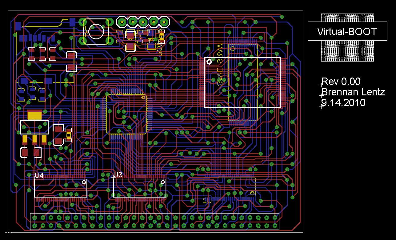
Also, I can’t really tell the difference between the screens, DogP. I guess I don’t really know what an autorouter looks like since I have usually done stuff by hand. When you have boards that dense, you’re going to have a lot of random vias and strange looking traces no matter what you do.
DogP wrote:
Did you actually route that all by hand? A lot of that looks very random, like an auto-router would do. Of course that probably happens when you’ve got lots of chips with pinouts that don’t exactly line up 😛 . And I disagree about using the auto-router… all the ones that I’ve used have sucked, and even if they do route, they look like crap 😉 .I mean… compare: http://www.planetvb.com/content/hardware/flash_carts/flashboy/images/fb_proto1_1.JPG with http://www.planetvb.com/content/hardware/flash_carts/flashboy/images/fb_proto4_2.JPG . I guess Richard could probably answer this… but the first one DEFINITELY looks auto-routed. Was that Electra? The second one looks possibly auto-routed but seems to have at least some manual routing (or maybe just some better auto-routing rules).
DogP


I let the Eagle router do its thing first (mostly cause I was just curious what it would do) and it only filled in about 10-15% of the traces. Then from there I modified some things and did the rest by hand. Probably took me 20 hours or so but it has still changed a lot since then. I got “in the zone” for a while at night, ended up staying up most of the night working on it. I agree it looks pretty bad and random. The problem is I would try running lines and almost immediately come across a trap, so I ended up having to use probably 2x more vias then I wanted and the traces are crossing each other all over the place. It’s so hard because as you know, there are several shared buses, and the pins of the SRAM are REALLY random and don’t follow any kind of logical order on the footprint. The PCB has changed quite a bit since I posted that screen, it’s an ongoing process.
MineStorm wrote:
Well, it’s safe to say this is the single hardest 2-layer PCB I have ever made
You are a masochist. I could have put it through my copy of Electra for you.
Haha, I guess I am. 😀
Electra looks like a pretty cool autorouter. I tried the demo version and it worked fairly well (only missed like 20 or so connections on a 2-layer board). The problem is you can’t export anything with the demo version, and I don’t have $130 to spare for a license.
Fwirt wrote:
Vaughanabe13 wrote:
Does anyone have the dimensions for a (original) gameboy cartridge off hand? I know it’s not the same as a VB cart but they are plentiful and I could potentially hack it and try to make it work. I personally don’t care about having a case for the cart, but I understand it’s an issue that needs to be addressed.No dice, VB cartridges are way thinner than GB carts. In fact, VB cartridges are just about the thinnest carts I can think of. You can fit a VB cart inside a Game Gear cart carrying case, unfortunately you have to rotate it 90-degrees so that wouldn’t work either. (Plus the fact that Game Gear carts are getting to be somewhat of a rarity too.) Personally, I’d be fine with a bare PCB, but from MineStorm’s comment, I would guess that that isn’t true for everyone else.
On a side note, I didn’t notice this thread when you posted it, really nice work dude. I probably wouldn’t be able to afford this any more than a FlashBoy (or an EPROM cart for that matter) but I was always wondering, “How would you go about making an SD cart?” I’m glad someone has the engineering skills to get it done. What are you getting your degree in?
Yeah, I finally got a calipers and measured the GB cartridge so I know what you’re talking about. Plus my board has to be bigger than the area of a GB cart anyway because of all the traces. The biggest physical-size problem I’m having right now is trying to figure out the VB connector. I have some connectors that are a very very close match, but they aren’t thin enough. So I have to sand away some of the plastic, but that weakens the integrity of the connector, and it also doesn’t have the two raised grooves that the VB cart does, so it might make insertion hard. I mean, theoretically once you put this cart in your VB you should never have to take it out (just the SD card, which can be easily popped out), but I can’t rely on that because some people will be using it on multiple VBs and may be inserting/removing it often. As far as the bare pcb goes, I’m afraid people have been spoiled by the great work Minestorm has done on the Flashboy and using donor carts. At this point I don’t think my cart will even fit inside a VB case, because I have to put components on both sides of the PCB, which increases the thickness.
Affordability is always going to be a problem with this kind of cart, unfortunately. The VB technology is really old and the components are rare and expensive. The board costs won’t be so bad if there is a high enough demand, because I can make large batches of PCBs and get a discount that way. It all depends on how many people are interested in something like this. I can’t imagine I would be able to make this cart any cheaper than $60-70 USD but it’s tough to say. Again, I don’t care about making a profit or anything. I might even put the designs and firmware out there for DIY people who want to order their own board and components.
Thanks man, I appreciate the compliment. I’m currently finishing my last semester of undergraduate work, so I’ll be graduating in December with a Bachelor’s of Electrical/Computer Engineering. After that I’ll probably get a Master’s through my company, but I haven’t decided what I want to focus in.
Well, it’s safe to say this is the single hardest 2-layer PCB I have ever made. It’s so incredibly dense I can barely even tell where everything is now. I still have a few sections that are causing problems but as you can see, progress is being made.

This is what I found about it from reading message boards:
“In most cases, the wear is gradual. You’ll notice the Dreamcast will go back to the BIOS / configuration screen and ask you to insert a game. Another telltale sign is an unusual amount of activity coming from the GD-ROM unit. That’s usually because the unit has to keep rereading the data it’s having a hard time picking up.
The problem with reading CD-R media stems from the way the unit was designed. The GD-ROM format is a high-density medium with a lot more data packed into the same area a CD-ROM would normally occupy. When you create a backup or otherwise, the format of the GD-ROM format is lost (if you look at a real GD-ROM disc, you can see a special protected area towards the center). The data gets misaligned and spaced out. This can occasionally be caused by writing the disc too fast or overburning.”
DogP wrote:
I’ve basically ONLY run CD-Rs on my Dreamcast and it still works.DogP
Same here, and I’ve been doing it for years with no problems. Then again, I bought the system for $20 on eBay and it’s not in the best physical shape, so if my laser ever goes bad I would probably just get a new one.
Doing the routing myself is actually my favorite part, and it’s free.